MIDIBass 303 Installation
Sync Mods
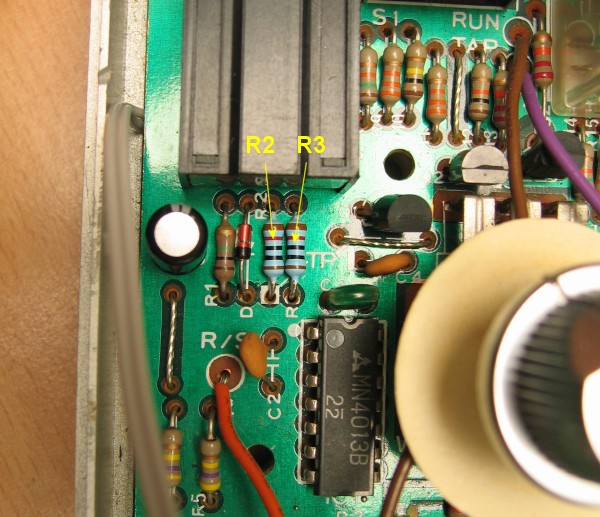
In order to allow the MIDIBass sync connections to safely over-ride the internal 303 sync signals, two resistors must be changed from values of 1K to 10K. These are resistors R2 and R3, shown here:
Here are the pads to de-solder on the underside of the board:
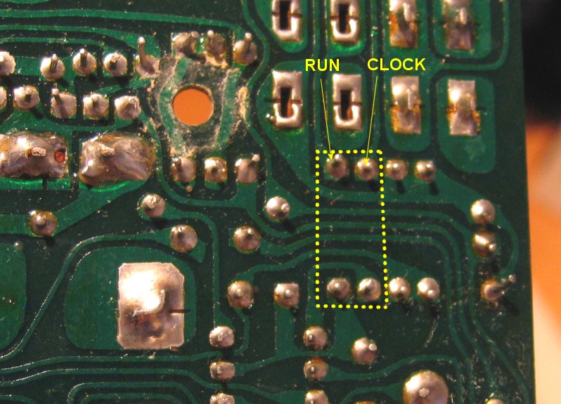
Once these resistors have been replaced, the extra capacitor must be added between R3 and ground.
This is required because a bug in the way the 303 CPU handles its sync signals means that sometimes the 303 will see the clock pulse before the RUN line goes high as the first clock pulse. You don't notice this using a 303 alone, but if you generate midi clock from the internal sync signals, your synced devices can end up one clock tick behind the 303 itself. The extra capacitor delays the start of the RUN signal so that the 303 knows the previous clock pulse has ended before it starts running.
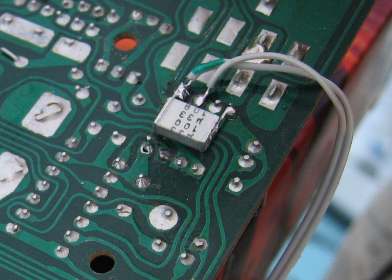
The extra capacitor is soldered to the pads shown here. Also shown are the RUN and CLOCK wires from the 2 pin connector on the MIDIBass board:
next page >>

Last update: 8th August 2007
MB303 home