MIDIBass 303 Installation
Before installing the board, I recommend a slight change to the 303 PSU circuit.
There is a current limiting resistor in the PSU, which can cause the 12v power supply rail to become unstable in some 303s once the MIDIBass board has been added.
This resistor can be safely replaced wtih a wire link to ensure you don't suffer from this.
The problem can be heard as a 'fluttering' of the filter cutoff as notes are triggered.
The resistor to replace is R172, which can be found just to the right of the VOLUME pot.
I replace it with the leg clipped from one of the 10k resistors used in the SYNC connections.
Fitting the Board
With all the board mods complete, you are now ready to plug in the MIDIBass board.
It's a tight fit, given the minimal available space, but it can be done.
To reduce the chance that the pressure of inserting the board may cause a fracture in the main PCB, it's a good idea to support the PCB with a piece of wood or a book directly under the 16 pins of the socket.
It's important to note that the ribbon cable connection from the switchboard to the mainboard must be run UNDERNEATH the MIDIBass board. It may also need to be pushed to the side slightly to allow the header to be inserted into the 16 pin socket.
Be very careful when you insert the MIDIBass board into its socket not to bend any of the header pins.
Some of the other ribbon cables may need to have their positions adjusted slightly to make room for the MIDIBass wiring.
When fitted, it should look like this:
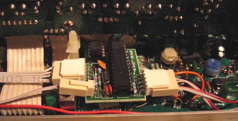
There is now just enough clearance to clip the switchboard back into position, although I'd strongly suggest testing everything is working first.
However, I've not yet mentioned the fitting of MIDI IN and OUT sockets.
It is possible to fit 5 pin DIN chassis sockets to your 303 case, but this requires drilling large holes, which will weaken the case considerably. There is only room to fit DIN sockets at the side of the case, which means they may also get in the way.
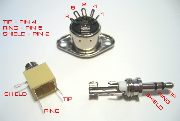
My preference is to use 3.5mm STEREO sockets for MIDI In and Out, and to either make up special 5 pin DIN plug to 3.5mm stereo plug MIDI leads, or short 5 pin DIN inline socket to 3.5mm stereo plug 'pig tail' leads that normal midi leads can be connected to.
I use the tip of the stereo plug for pin 4, the ring for pin 5 and the shield for pin 2 (midi out only).
This image shows the wiring I use:
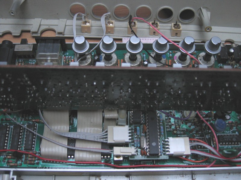
By using 3.5mm sockets, the midi connections can be fitted to the rear of the 303 case, between the knobs, in the location usually used to fit CV/Gate input sockets. In fact, if you've already fitted a CV input mod kit to your 303, it's likely that you can replace the CV/Gate input sockets with the Midi In and Out connections without the need to do any futher drilling.
This picture shows a 303 which had a 5 socket midi retrofit installed. All but the filter CV input has been removed, and two of the input sockets have been replaced with the Midi In and Out sockets for the MIDIBass board:
Once everything is fitted, and tested OK, just close the case back up following the reverse of the disassembly process, watching that none of the new wires get caught in the case screw mounts.
If you have any questions about the installation procedure, just drop me an email.

Last update: 8th August 2007
MB303 home