Tuning A Discrete Minimoog
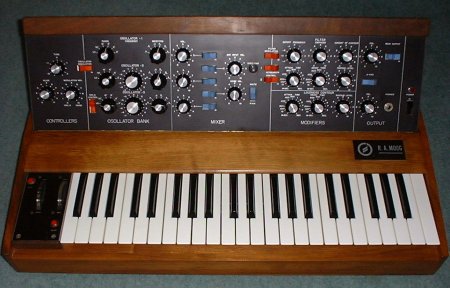
Some time ago, I was lucky enough to pick up an early RA Moog minimoog, built at the company's Trumansburg factory.
The first minis were built entirely from discrete components, without a single integrated circuit.
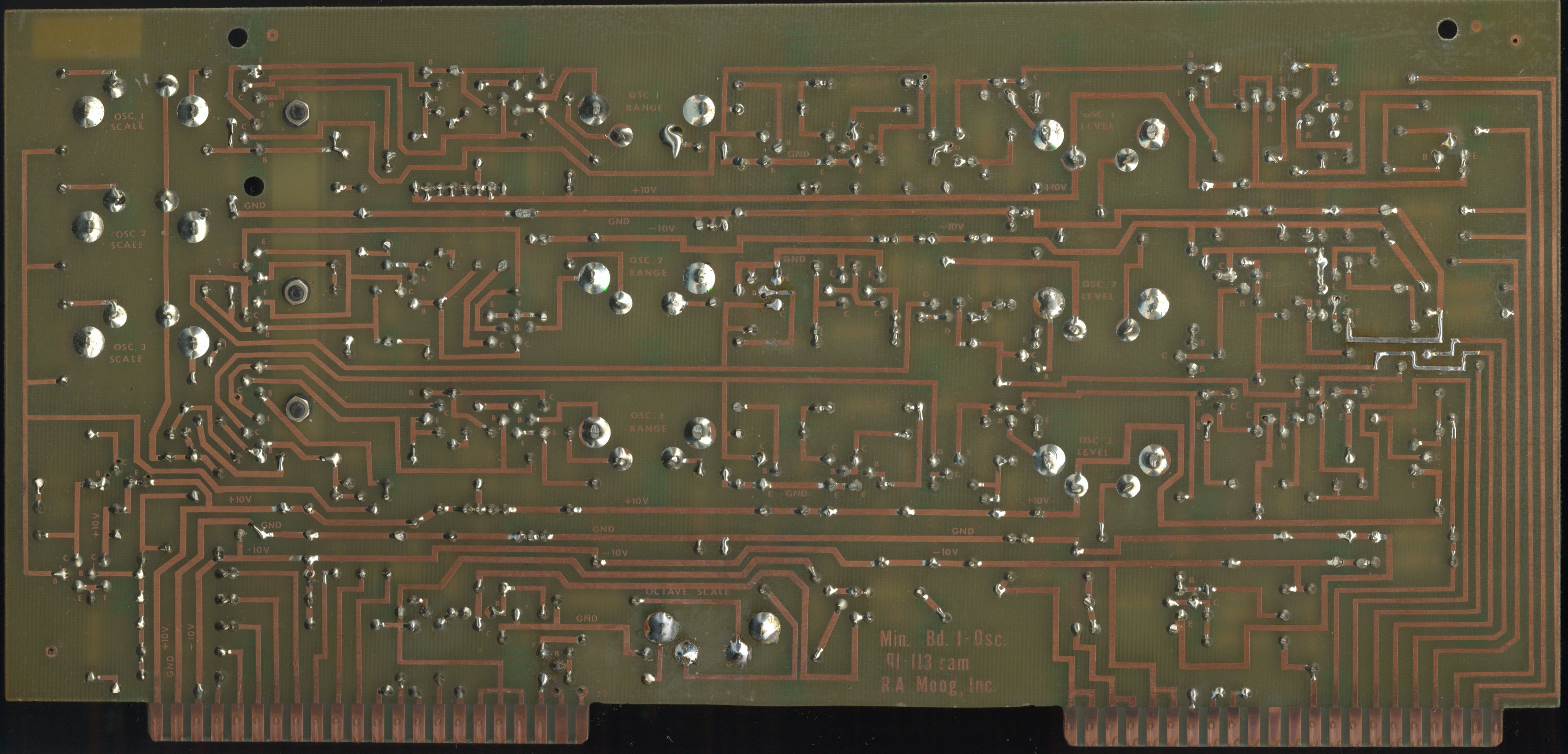
Although many minis were 'upgraded' with later boards, mine has retained it's original discrete vco board as shown below.
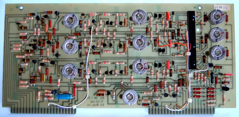
click image for rear view
Only problem was, the service manual makes no mention of this board, it has a very different PCB layout, and three extra preset adjustments for tuning labelled LEVEL.
After spending some time with the schematics I worked out what these extra 'level' controls were for, and how they are involved in the adjustment process.
The level controls set the gain of the buffer amp after the sawtooth core of each oscillator.
The level of the sawtooth has most effect on the sawtooth to triangle wave convertor. If the level adjustment is wrong, there will be a step in the triangle wave at its positive peak, that alters the sound noticeably.
Once the level control is adjusted for the correct triangle wave shape, the range and scale controls can be adjusted as per the normal vco tuning procedure.
This image indicates the three points (at the left hand side, in red) on the circuit board where the triangle wave can be found for each oscillator.
Hook a scope up to each of these points in turn, remembering to hook up the earth probe too - an audio jack shield will do, then adjust the level control (the leftmost controls) until you see a proper triangle wave, without a step.
Once that's done for each vco, continue with the range and scaling as usual. There are plenty other sites on the web that will tell you the rest of the procedure.
The Range controls are in the centre, the Scale controls on the right.
The octave scale is just below the range controls.
Minimoog oscillator board wiring diagram (651k pdf)
Note that this wiring diagram includes the buffer board and octave range selector resistors for later minis.
The earliest boards do not need the buffer board, and use four 10R resistors and one 47R.

Last update: 18th March 2008
home